|
Special Hobby 1/72 Piaggio P.108A |
|
|
Kit Number 72065 |
|
|
Reviewed By Brian R. Baker, #43146 |
|
|
|
|
|
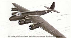
MSRP: $54.00 USD Review Sample Courtesy of Special Hobby. HISTORY The Piaggio P.108 heavy bomber was the only four engine bomber to see production and service in the Italian Air Force during World War II. Bearing a superficial resemblance to Boeing’s early model B-17 “Flying Fortresses”, the aircraft was somewhat more advanced in some details. In fact, the designer had worked in America for Boeing back when the early B-17’s were being developed, and apparently many of the conceptual ideas went with him when he returned to Italy before the war. The airplane was not particularly successful, and only 163 were built, hardly enough to affect the outcome of the conflict. Besides several variants of the standard bomber version, several transport versions were built, most of which apparently were taken over by the Luftwaffe and used in Russia in the latter stages of the war. Apparently one was captured and flown in USAAF markings towards the end of the war, but none survived the conflict. This kit depicts a “one off” variant, the P.108A, the “A” standing for “artigliere” (artillery). This variant had a modified 102/40 mm. naval cannon mounted in the nose, firing at a slight downward angle. Provision was made to carry 47 to 50 rounds of ammunition, which had to be hand loaded, and the aircraft was intended for the anti-shipping role. The conversion was done between December, 1942, and February, 1943, and trials were conducted at the navy firing range at Viareggio, and later at Furbara Air Base, Italy, in the spring of 1943. It was not used operationally, and no further conversions were made. Although the armament was satisfactory, and could be fired without adverse effect on the airframe, a gunsight was never installed! In September, 1943, the prototype was taken over by the Luftwaffe, who flew it to Rechlin, where it was subsequently destroyed in an Allied bombing raid. One unusual feature of this aircraft was a remote gun turret arrangement, the gunners being located in dorsal positions in the fuselage, while the twin 7.7 mm. machine guns were located in Breda Z.2 turrets located in the rear of the outboard engine nacelles. These remotely controlled gun turret systems apparently were quite troublesome, as can be expected with any type of new technology. Possibly they were developed because the airplane did not have a manned tail turret, a carry over from the early B-17 design influence. THE KIT This kit is an example of some of the recent products of the Czech Republic Model Manufacturing Complex. It consists of 83 parts in light grey plastic, 12 clear transparencies, and at least 30 resin parts. Some parts will not be used, and for some reason, cowlings for 8 engines are provided, in case you want to make the “Zwillingi“ modification. The moldings are crisp, with very little flash or sink marks. The outline appears to be accurate, and when finished, it “looks like the airplane”, so I had no complaints in that respect. The resin parts are particularly nice, and although one gun barrel was slightly warped, this was not a problem since there was an extra provided that was not used. The cockpit details, including the very nicely detailed seats and control wheels, are very well done. Two instrument panels are provided, and these are easy to paint, as they have the instrument holes recessed enough to hold a drop of black paint for the instrument faces. The transparent cockpit canopy in very clear, so the details inside can be clearly seen. In fact, the kit has parts for all three major versions, with nose transparencies for the two bomber variants, so you could actually build any of the variants with any kit as long as you could improvise the decals. The only real difference between this kit and the standard bomber kit is the instructions and the decals. The decals provide markings for the same aircraft in both Italian and Luftwaffe markings. Quality is excellent, and up to the highest standards. They even provide a decal for the white tail cross common to Italian aircraft, although this was so simple that I opted to paint and mask rather than use the decal, as the white fuselage band is not provided as a decal, and has to be painted anyway. The little crest is provided separately, so it was no problem putting it on after the major painting was done. In short, decals were excellent. INSTRUCTIONS The instructions cover 13 pages of kit related material, with the back page advertising some of the other kits produced by Special Hobby. A history of the airplane is given in English and Czech, along with a sprue diagram that identifies the parts, although one or two parts that aren’t used are not crossed out while others are. Some of the diagrams are a little misleading, but nothing that an experienced modeler can’t handle. The diagrams show the area of the model being assembled, not the order of assembly, which could present a problem if you don’t read the instructions carefully. In the case of the small side windows, I discarded them and used Krystal Clear after the model was completely assembled and painted. There were a couple of parts that I could find no use for, such as Part No. 10, which I THINK was part of the pitot tube assembly, although there is no reference to any pitot tube in the instructions. I finally found a photo of the nose of the P.108A and discovered that the pitot tube was located on the front of the forward radio mast. Also, the instructions show some kind of tail-wheel cable or rod assembly located at the rear of the tail-wheel fork, running upwards into the rear fuselage at about the rudder hinge line. Photos of the airplane show this too. There is no part provided for this, although a short piece of plastic rod solved the problem. A major problem in the instructions is the color information. The colors are given in “Gunze” codes, and for those of us that do not have access to this brand of paint, it leaves a lot to guesswork. I had to work out a color chart, but I’m still not sure about a couple of the colors. I assumed that the interior of Italian aircraft was a pale green color similar to the RAF interior green, which is what I used, but I may be wrong on this. Most model producers give a variety of color systems, including RLM, RAF, US, and FS codes. This would have been helpful. REFERENCES This kit requires adequate references if you are to built an accurate model. While I was in Albuquerque for the IPMS Regional, Chili-Con, last month, I stumbled upon an Italian publication, IL PIAGGIO P.108 by Giancarlo Garrello. Although written in Italian, it has a lot of good interior and exterior detail photos, and a good three view drawing of the aircraft. It was kind of like reading a Koko-Fan book—lots of pictures, but it lets you know what it would be like to be illiterate, a scary thought. This book was very useful. In addition, a few years ago, Squadron-Signal published a paperback book, ITALIAN AIRCRAFT OF WORLD WAR II, by Nico Sgarlato. Although coverage of the P-108 is fairly brief, some useful information is presented, including a cutaway drawing of the P.108B, which except for the nose, is identical to the P.108A. ASSEMBLY Assembly of this kit is straightforward, although you have to become VERY familiar with the instructions. The cockpit interior is easy, although one control column is longer than the other. There isn’t much information on the details of the instrument panel or other cockpit interior details. The fuselage is braced by a couple of interior bulkheads, one of which serves as a wing spar to strengthen the wing attachment to the fuselage. This needs to be trimmed somewhat to assure adequate fit. The rear bulkhead location is a bit confusing, as it needs to be ahead of the little side window in the rear section of the fuselage. Also, the side window panels, apparently for a waist gunner’s position, need to be installed from the inside before the fuselage halves go together. The top gunners’ positions should probably be installed at this time, even if you don’t put on the transparent tops until later. These are resin, and should be super glued in place at the proper angle. And last, the tail-wheel fork, a resin part, needs to be super glued inside of the tail section before the fuselage halves are joined... check the drawings to get the proper angle. This part just begs to be knocked off during assembly and handling, but I managed not to do this. I lucked out on that one. Once the fuselage is joined, some filling and re-scribing is necessary, bit the parts fit quite well for this kind of kit. The wings consist of two parts each, and are perfectly matched, only requiring some sanding and filing to clean up the edges. Be sure to line up the oil cooler intake holes in the leading edge. When assembled, the wing panels line up perfectly with the wing roots, but you have to slide the spar section into a special receptacle in the wing interior. It is difficult to get any glue into the wing area, so the main glue joint will be at the butt, but the overall structure is very sturdy nevertheless. I would advise installing the gun turrets in the top wing sections before joining the wing sections, lining them up so that they are completely level. They should be level, both laterally and longitudinally. At that point, the engine nacelles are ready to install. They fit very nicely onto the wings, with the only filler needed being on the joint where the inside nacelle sections join together. Be sure to glue the firewalls and wheel slot together first, and install them in the nacelle sections after they are joined. The faceplates are in two sections. Although the instructions don’t say how to do it, I glued the firewalls with the wheel slots into the forward section of the engine mount disk, and then glued that section onto the front of the nacelle. If you try to mount the firewall directly to the engine nacelle, you’ll find that it doesn’t fit, but mounting it to the forward disk assures a secure mounting. For the outside nacelles, just glue the forward engine mounting disk on to the front of the nacelle, followed on all four engines by the tapered engine mounting disks. The engines need to be detailed, and the cowling interiors should be painted the interior color or silver---there are no instructions here. When the cowlings are joined with the engines mounted in the proper position, smooth out the joint lines and the cowlings are ready to be installed on the airplane. The tail unit is almost a no-brainer, but be sure to note that the horizontals have an airfoil, and that the more curved section goes on top. It is easy to line this up, as the wings should already be in the proper position. Once the major airframe components are assembled, it is time for the details. The nose section almost fits, but will require some filler. Leave the cannon barrel out until after the airplane is painted. The cockpit canopy can now be attached, making sure that there are no gaps. I left the three turrets off until after major painting was done, although it might be best to at least install the lower portions of the turrets. These are resin, and should be super glued into their positions. If you wait until last, you might push them through too far, and they will drop into the interior, never to be seen again. I got away with this, but next time, I’d put the top turrets in before joining the fuselage halves. PAINTING THE AIRFRAME. At this point, I did the required masking and painted the airframe. The undersides should be the standard Italian blue grey, which Model Master has available. The upper surfaces are supposed to be an Italian dark green. All of the color drawing’s I’ve seen on this aircraft show a dark green, not similar to the Model Master Italian dark green, but much darker than that. I thought about that for a while, and wound up using Luftwaffe RLM 73, which is, in Model Master colors, similar to the color on the box top. I’m sure it was actually an Italian color, but I had no references. The Luftwaffe version of the plane was the same color, with only the markings changed. DETAIL INSTALLATION The landing gear is rather easy to install once the wheels are trimmed down to where the struts don’t bow out at the bottom. I used a drill on the main wheels to make the wheel hubs slightly thinner. After painting the wheels, I slid them into position on the strut and attached the struts to their mounting locations in the wheel wells. I found it necessary to drill out and enlarge the mounding holes so the gear struts had some solid mountings. The gear doors just butt mount directly to the outsides of the nacelles. They are easy to align. The engines can be mounted directly onto the nacelles, using the little marks inside the cowling as a location guide. Be sure that they are mounted straight, as they look funny if they are off center. The crankshaft should extend just ahead of the front of the cowling. They can be misaligned, so be careful here. The props are a problem. They consist of four resin hubs, and 12 blades. These are supposed to join on the hub with a small hole that the butt of the prop blades should fit into. They don’t fit very well, and should be trimmed BEFORE they are painted or mounted on the prop hub. I painted mine, and then applied the decals. I also enlarged the mounting holes, and drilled out and enlarged the holes, but the real trick would have been to reduce the diameter of the prop bases so that they would fit into the holes in the prop hubs. Since the hubs are resin, and the blades are styrene, superglue is essential here. The hubs can be painted silver, while the props are black with yellow tips. The decals for the props are rather colorful, and I’d advise applying the decals before attaching the props to the airplane. The props need to be aligned for direction and pitch. It would have been a LOT easier for them to just cast single piece props. Other details include the machine guns in the turrets, the radio mast, the fuel drain tubes on the outsides of the inboard nacelles, and the other small details. After painting, the top turrets can be installed, along with the lower ventral turret. This should be drilled out to accept the machine gun. DECALS The airplane, being painted, can take two different sets of decals, as it is basically the same airplane with two different sets of markings. The decals are of excellent quality. Once the decals are installed, the plane is almost finished. Don’t forget some of the small pieces, especially those shown in the drawings but not on the instruction sheets. I used stretched sprue for the LF antennas, mainly because I couldn’t get wire to stretch that far. I would have preferred wire, but sprue looks OK. FINAL COMMENTS This is not an easy model to build, but it is unique, and any collection of World War II aircraft should include at least one. I can’t imagine any other company issuing one in 1/72 scale in the foreseeable future, so this looks like the only show in town. I would highly recommend the model to serious modelers. At almost fifty bucks a crack, you’ve GOT to be serious. |
|
) |
) |
) |
) |
) |
) |
) |
) |
|
Information, images, and all other items placed electronically on this site are the intellectual property of IPMS/USA ®. |
|