|
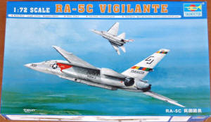
Trumpeter 1/72 RA-5C Vigilante |
|
|
Kit Number 01616 |
|
|
Reviewed By John R. Lee, #11172 |
|
|
|
|
|
MSRP: $29.95 USA Well after years of begging for a new Vigilante kit other than the 1/144th (I have built four of them) and the old Revell 1/72nd kit, we are hit with a bounty of them, one each in 1/48th and 1/72nd. This kit comes in a large, sturdy two piece cardboard box great for holding parts as you build, containing four medium gray sprues, two are identical. One clear sprue with 19 crystal clear parts of which six parts I will replace with Micro Kristal Klear. Four loose individual medium gray parts of the two fuselage halves, tail and the underside canoe, which is, called a “Cabin” on both of the kit assembly instructions. One decal sheet with two aircraft schemes (I sure many will say it is too light, but I just look at them as if the aircraft have been out in the sun and elements awhile) and one film for the instrument panels. I do have both Trumpeter Viggie kits and the assembly plans are almost the same for each with the only difference being for the extra parts in the 1/48th kit. Both the kits have the trailing edge flap parts separate but only the 1/48th scale kit has the leading edge slats separate and as they work together on the real aircraft I will build mine raised. Maybe an after market company will come out with separate slats and a new set of instrument panels – more later. Also, after looking through the five reference books I have I see that most Viggie’s are actually parked with the flaps and slats raised and canopies closed but even on land the wings are quite often folded. The rivet master (Transferred from Matchbox maybe) had fun with these kits – there are thousands of them all over the model. The kit I received had minor flash on almost every piece that I needed to scrape off before many of the parts could be placed. Several of the parts are attached to the sprue with large gates that require the careful removal so as not to damage the part. This does create a problem for a lot of the very small parts in removing them from the sprue. I am lucky in that I have a friend that sells dental supplies and I buy boxes of 100 #11 blades, so I was able to change blades frequently. |
|
) |
) |
) |
) |
| Let’s get on with the building of this critter. As usual we start in the two seat cockpit that has 27 parts along with 10 parts for the nose gear, wheel and wheel well and 5 pieces for each bang seat. First off, let me say three very important words “DRY FIT EVERYTHING”. Right off the bat I found that there are an abundance of ejector pins that will need to be sanded flat in all wing, rudder, and horizontal stab parts to allow them to fit. I did cover some up in the cockpit just in case they would show. I also added a couple of black boxes as seen in my reference books. There are a lot of fit problems in the cockpit that require trimming to allow the parts to go into place; among them are C9, C14, C30 and C33. I believe that a lot of the problems stem from the “draft” angle built into the molds to allow to parts to be removed from the molds. On these parts I just squared them up and all was ok! The whole cockpit is built on a long floor part C31 that fits perfect. I placed the floor temporally into the left side to get the proper angle of the back seat parts C3, 9, and 30 combination snug up to the inside top of left fuselage half. I applied some Tenex and left it over night to really dry solid. As with the back seat area I placed the front instrument assembly up against the left side of the fuselage and again applied some Tenex and let it dry over night. I find it interesting in the way Trumpeter did the six instrument/switch panels. They are a good fit, look realistic, and painted up nice. I masked off the sides of the built up cockpit and sprayed the nose wheel well area Model Master insignia white along with several other parts still on the sprues and all of the wheels. If done this way don’t forget to place a piece of masking tape over the two slots for the front bang seat; otherwise, unless you have already installed the seats, you will have white paint all over the cockpit. As I plan to leave the canopies down the pilots and RAN’s instrument panels are ok as they come. Unfortunately, to me the RAN’s panel looks the best but is the hardest to see with the canopies down. In the photos you can see that the holes for the film to show through are quite deep and make it hard to see the instrument faces. | |
) |
) |
) |
) |
| Moving on to step Four - installation of the two ejection seats. As you can’t see much in the cockpit I used some spare propeller aircraft Airwave seatbelts to dress up the seats. I used the “Mini Hold and Fold” tool to make accurate bends in the Airwave parts and it works great. I found out that the seats were way too wide, so I trimmed off all the beautiful detail on both sides of both seats. They then fit ok and were glued onto the floor. I then assembled both main wheel wells. Parts #D10, B34 & B35 needed to be trimmed a little to square up the parts. One of the best fits is where both of the main wheel wells go – no problems, I just held in place and dabbed on a little Tenex and clamped them for awhile. I had made and painted both of the engines/tailpipes, which I must say look very nice, but I heard they are wrong for the Viggie. With a little bit of minor trimming I could see that they could be installed last after the model is nearly done, avoiding a nasty masking job, so they were set aside. Next I put the cockpit in one fuselage side, lined up the other side, and found that the cockpit seemed too wide. After studying the problem a bit I saw that the molded in stringers beside the back seat on the fuselage sides was the problem. I cut a very small part of the stringer off and all was ok. I then placed the cockpit assembly in the left fuselage half. It was a perfect fit. | |
) |
) |
) |
) |
) |
) |
| In step Nine I added the windows to the canoe pod and added part B8 & B9 to the main gear legs. Again part of the clevis-like area on both main gear legs needed to be trimmed a lot to allow part B8 & B9 to sit level. The two small side windows also needed a little filler to match the canoe’s surface. As I said above, “Dry Fit”, which I did and as seen in photo #21 you can see where the fuselage halves apparently collapsed when removed from the mold, maybe because the parts were too hot to hold their shape when removed. I cut off a couple of pieces of the larger sprue a little longer than what I needed and slowly, ever so slowly, sanded the end down and kept fitting them into the fuselage halves until the parts were pushed out enough to make everything square. I then glued the fuselage halves together. Not the best fit, as there was a little ripple in both halves, so I used Tenex for about ˝ to ľth of an inch at a time. I then held them in alignment while the glue set. Thanks to the fast drying time it worked out well, although as the seam is about 6 ˝ inches long, it took a while to complete. Next I glued the bottom join together. This is an even worse fit than the top but it’s ok, as the canoe will cover most of the seam. As seen in Photo #25 the top seam finished out good. I didn’t finish the seam area under where the rudder will go, as it seemed unnecessary. I left the main gear legs off until later to avoid the possibility of breaking them off - but note that in step 11 the plans have you installing the retraction jacks and some of the gear doors before the main gear legs are installed in step 12. Most kits I have put together have fairly flat or square gluing mating surfaces - not this kit. The fuselage edges are at such an angle that to sand them flat the fuselage would have been reduced in width quite a bit if scaled up to full size. If you look close you can see a “V” gap where the parts meet right under the “5” on the six inch scale in Photo 24. Doesn’t leave much of a gluing surface! | |
) |
) |
) |
) |
) |
) |
|
I put part C20 in place after a small amount of trimming to get the end of it to match the length of the fuselage. After drying I sanded the seams down. Next came the tailpiece with a good fit and just a little filler needed. I had painted the wheels Model Master insignia white earlier. Now that they were dry I used my Verlinden stainless steel scribing template, cut out six circles of masking tape, and placed them over the white wheels. I then put the tires together and stuck a toothpick in the axle hole, and shot then with Gunze tire black. While I was at it I brush painted the edges of the landing gear doors Humbrol red. |
|
) |
) |
| Next up is to put on the cabin/canoe on and when I offered it up to the lower fuselage I saw that the back end of the cabin/canoe had what looked like a bird’s beak. I cut off the locating pin and drilled a .040Ř hole where the pin had been and sanded that end of the cabin/canoe to match the lower part of the fuselage. I cut off a short section of tubing and super glued it into the previously drilled hole. I then glued it to the fuselage and all was good at the Lee household. | |
|
|
|
|
I now joined all the wing inner and outer parts, the horizontal stabilizers, rudder upper and lower parts and the flaps, which all
required sanding on the inside surface to flatten out the ejector pins. Minor adjustments also had to be made to several of
the flap parts so they would fit to the wings. The top and bottom of the rudder needed a lot of careful trimming so that they
would fit together nicely. I let these parts dry for a couple of days and then sanded down the leading edge joins. I found it interesting in that Trumpeter put bubble wrap around the intake parts. I could see that there would be a need for some sort of “blanking” plate in the intakes as nothing was provided in the kit to stop a see though. I decided to make some FOD covers for the intakes. I used some .020 Evergreen sheet and after gluing them in place I drilled four holes in the face of each FOD and inserted pieces of bent staples for the handles. I then painted them Humbrol red and when dry, covered them up with masking tape for the remainder of the painting sessions. |
|
|
|
|
| I masked off the canopies and glued them on to keep any over spray out of the cockpit. I shot them the interior color, FS36231. I then painted the underside of the fuselage insignia white and let it dry a couple of days (it’s cool and humid this time of the year here and it takes longer to dry). I then masked the insignia white off so I could finish painting the area that would be under the intakes gull gray, along with the front of the fuselage. Maybe a little odd to do it this way, but I have never been able to airbrush successfully behind the intakes of a model. I then jumped ahead to step 20, and installed the air intakes. By the way make sure you screw down the lid of your paint bottle before you shake it up to mix it like I didn’t with my Model Master insignia white paint. | |
) |
) |
| I decided to paint the rest of the sides of the fuselage gull gray at this time to save painting into a 90° corner with the wings in place. In Photo #43 you can see that the canopy is a bit narrow. I also saw this with the 1/144th Trumpeter F-86F that I built. I also painted the undersides of the wings, tails and top areas requiring insignia white and again let them dry for a couple of days. I had forgotten the trick of drying paint faster by using a small lamp or a hair dryer – next time. I used a different pattern for the white on top of the wings than what was on the plans. Several of the pictures and diagrams in my reference books show the demarcation line between the wing upper colors starts about mid way of the wing tip and runs in a straight line to the wing root at the inboard flap line on several aircraft. | |
) |
) |
| The part for the fuel dump pipe is a butt fit to the left lower rear of the tail cone (Photo #44). I drilled out the area and after all was painted and decaled I put in a piece of .040Ř stainless steel tube to represent the dump pipe. I left it unpainted, as in the pictures in my references it appears to be unpainted. I sprayed a little bit of thinned Tamiya smoke on the tail cone for the exhaust stains seen in pictures. | |
) |
) |
| I added the wings to the fuselage, which did require a small amount of trimming on each to get them to fit right. After filling the seams and sanding them down, I re-scribed the panel lines. I masked off all the areas on the wings and tails that will remain white and finished off the topside Model Master gull gray. After the paint had dried, I masked off the slat area and painted them Model Master stainless steel. Next I masked off the area for the forward receiving antennas and painted them Model Master insignia white as seen in several pictures. With almost all the painting done to all the bits and pieces it was time to bring this beast alive. On to many modelers (and my) favorite thing, putting on the decals. I used an Aeromaster star and bar for the upper left wing as the way the kit two piece decal was to be placed put it at the wrong angle to the wing. All in all, the decals went on great - I only used Micro Set - and they settled into the panel lines and abundant rivets without the use of a setting solution. After the decals had dried overnight I washed off the excess decal solution. I then added the horizontal stabilizers. A little trick I learned is to use a set of X-Acto clamps as a height gage to have both tail surfaces and wings for that matter the exact same height as seen in Photos 52 & 53. They can also be used as a support while the glue dries as you can see by the clamp to the right in picture #52. | |
) |
) |
) |
|
|
All that is left is to paint the anti-collision beacon Tamiya clear red and add it, the flash pods and fuel dump pipe, and we’re done. I used the flasher pods to add a little life to the Vigie, although they were not used very much. The kit also comes with a pair of Mk-28 and Mk-43 special stores that were test fitted to the 'C' version of the Vigilante but were not used in service, so I added them to the parts box. One thing of note is the way Trumpeter molded the Vigie’s fuselage. It looks to me like they used at least a four-part mold, one for the inside and three to be able to produce the beautiful detail on the sides of the more or less rectangular fuselage. This left a raise lined running down both the upper and lower corners of the fuselage from front to back to include the tail cone part. This is also seen on the 1/48th kit. |
|
) |
) |
|
The rest of the photos are a walk around of the finished model with everything up and the wings folded. I like the looks of it this way other than the wings folded. It looks like it is going Mach 1.5 just sitting there. This is one beautiful aircraft and I am glad to have had the chance to build it and to add to my model shelf! Yes, there are several minor problems with this model but this is a complicated aircraft to mold and I think it will appeal mainly to modelers that have the experience to solve those minor problems and they will end up with a very nice looking replica of one of the US Navy’s most important Vietnam era reconnaissance aircraft. |
|
) |
) |
) |
) |
) |
) |
|
|
|
| Many thanks to IPMS/USA, John Noack and Stevens International USA, who are exclusive US Importers for the Trumpeter line of models: 706 N. White Horse Pike Magnolia, NJ 08049, (856) 435-1555, e-mail: info@stevenshobby.com. Web: www.stevenshobby.com for the kit, a great addition to my model shelf. | |
|
Information, images, and all other items placed electronically on this site are the intellectual property of IPMS/USA ®. |
|
)
)
)
)
)