|
Roden 1/72 Curtiss H-16 |
|
|
Kit Number 049 |
|
|
Reviewed By Jim Pearsall, #2209 |
|
|
|
|
|
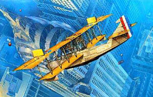
MSRP: $21.98 USD website: www.rodenplant.com Thanks to Roden for providing this review kit. Other Kudos I haven’t built a Great War aircraft kit for several years. But Brian Baker did a seminar on “aircraft rigging” at a Craig Hewitt Chapter meeting, and I decided that I really wanted to do one of these. When John Noack sent out a list of available kits, the H-16 was my pick. I also owe a huge debt to Jim Woody, who is probably still working on his Felixstowe F.2A. More on Brian and Jim later. The Aircraft As World War I progressed, the British found they had a winner in the Felixstowe F.2 flying boat. Good performance, maneuverability and endurance were the pluses for this aircraft. Several British manufacturers were contracted to build F.2As, and the Curtiss Aircraft Company in the USA was also given contracts to build a modified F.2A, with American Liberty engines instead of the Rolls Royce Eagles of the F.2A. When the US entered the war in 1917, the US Navy ordered H-16s for their use. The first H-16s were delivered to the Royal Navy in early 1918. The RNAS was the largest user of H-16s. By 1919, with the need for combat aircraft hugely reduced and the effects of salt water corrosion becoming evident, the RN struck all of their H-16s from the lists. The US Navy continued using a few of their H-16s until the mid-1920s. The box art shows an H-16 flying over New York City. Since the easily recognized Chrysler Building wasn’t completed until about 1928, this shows the H-16 at the very end of its’ career. The Kit The Roden H-16 kit uses an engineering trick which I really appreciate. Where there are multiple parts, like machine guns, props, engine parts, struts, exhaust pipes, there will be multiple sprues, all exactly the same. There will be enough sprues to provide all the parts needed. Once you find the part you need, it will be in exactly the same place on the other sprues. Example: You’ll need 2 props, either 2-bladed or 4-bladed, depending on which version you build. There are 2 sprues, each with a 2-bladed and a 4-bladed prop. An excellent method to reduce mold-making costs. The sprues can be seen at the Roden website. |
|
|
|
|
|
Assembly begins with the 2 Liberty V-12 engines. Each of these is a petite little project in itself. Cylinders, heads & rocker arms,
exhausts, crank case halves, intake manifold, radiator, coolant pipes and starting crank are all separate parts. The instructions
give 23 steps for assembling the entire aircraft, and the engines are the first 8. The fuselage and interior assembled with no problems. I picked up a trick of over painting a light enamel with a dark acrylic to simulate wood grain. |
|
|
|
|
|
The vertical and horizontal stabilizers were pretty conventional, except now is where this project moves from the mundane to the
exceptional. Rigging I put the control horns on the elevators and rudders, then painted the elevators with the bright yellow. Love that bright yellow. I then put on the control wires which run from the horns to the elevators and rudder. Brian Baker showed a great method for installing rigging. It requires very fine wire, and a steady touch. I discovered that the fine wire was easier to achieve than the touch. I began with a foot of #18 stranded wire. This is the standard wire used in extension cords and light appliance cords. I found some with silver wire and a clear insulation at Lowe’s for 16 cents a foot. When was the last time you paid less than a quarter for something to use in a modeling project? I removed the insulation with a #11 blade, and teased a number of strands out of the wire bundle. They come out twisted and in no way useful for rigging a biplane. This is where Brian’s second method comes into play. Cut a strand of wire slightly longer than the piece you need. Lay it on a fairly hard flat surface. Use another flat item to roll the wire perpendicular to its length. A couple of tries will generally give a perfectly straight wire. An addition: After I finished this kit, I showed it to Brian. He noted that the wire wasn’t very straight. THEN he told me he uses a very fine steel wire, not strands from an extension cord like I used. His wire is quite stiff, but as fine as what I used. Turns out he got his wire from a chip manufacturing plant, where it’s used for the contact wires on subminiature components. Step 3. Use dividers to measure the exact length to reach from point A to point B. Cut the wire to this length. Place a drop of Elmer’s glue at one end point of the wire, and a second drop where the other end will go. Touch the wire to point A, then convince it to touch point B. This is the step which requires huge amounts of patience, experience, and a very steady hand. I discovered I shake like it’s 40 below outside and the heat’s off. I couldn’t get the glue to hold the wires. Plan B: A tiny bead of CA, and use accelerator. Faster and solid. I also discovered that if you hit the end of the wire against anything while manipulating it into position, it bends, and is useless. If you do this at point B, you have to remove the cured CA at point A and start over. Imagine my dismay when I figured out that I had put the control wires on the rudder, and the US tri-color rudder band decals went under those wires. Pull them off, put the decals on, and do the wires again. This kit requires planning, planning, planning. The Wings The wings are the largest and most complex assemblies on the aircraft. They also present the biggest challenge. Each wing comes as 3 sections, center, left and right, and the top wing also has separate control surfaces. I assembled the wings, and then discovered the handiest tool for building this kit. Jim Woody’s review of the Felixstowe F.2A has a description and drawings of how to build an assembly fixture for this kit. I downloaded it and built it out of foamcore board. Jim used light wood for his, but I found the foamcore was light, and just as useful. I painted and assembled the lower wing and fuselage, and put them in the fixture. I glued the struts to the lower wing. I then assembled the upper wing, painted it and put it in the fixture. It fit pretty nicely with the lower wing and struts. In the picture below, the struts have not been glued to the upper wing, so alignment is off on a couple. |
|
|
|
|
|
I got the struts aligned and glued in. This was somewhat more difficult than I’m used to, as Roden doesn’t provide clear, deep
sockets for the struts. They’re merely dimpled spots. It required bright lights and a magnifying visor to get all the struts in
place. It was at this point that I discovered that the assembly fixture would also hold the aircraft inverted. I then put the decals on the upper wing and installed the engine assemblies. I had some trouble here, again due to not knowing what the assembly required. I had assembled the engines several weeks before, and had no real idea of how the engine mounts fit with the upper and lower wings. It took a couple of hours working with the engine mounts and wings to get everything to fit fairly close. More Rigging I discovered another scale effect after I got the wings mated. The aircraft actually requires rigging to be solid enough to stand up to handling. Fortunately I didn’t break anything, but keeping the model in the fixture while assembling is a plus. I rigged the areas between the wings, except where the fixture was in the way. |
|
|
|
|
|
It begins to really look like an airplane I now added the horizontal/vertical stabilizer assembly. |
|
|
|
|
| And there’s more rigging. On top of the wing and from the top of the lower wing to the bottom of the top wing. This task was made more difficult by the instructions, which didn’t have a complete rigging diagram. The text says to use the box art to complete the rigging. Unfortunately, you can’t see everything in the painting, and I’m pretty sure some wires were omitted. | |
|
|
|
| One feature of the H-16’s control wires was that they split between the fuselage and the control horns. It was necessary to do a splice of the wires. Good old CA. I did remember to put the decals on the fuselage side before I put these wires on. | |
|
|
|
|
Also notice that the aircraft is now sitting on top of the fixture, as I added all the rigging between the wings. I finished the model by adding the wires from the nose to the wings. Because these wires are pretty long, I had little luck getting them really tight. |
|
|
|
|
|
Recommendations If you’re thinking about buying this kit, even to build later, download the plans for the fixture from Jim Woody’s F.2A review here at the IPMS/USA web site. Also, buy the Osprey book on the Felixstowe. I didn’t, and this probably made the build more difficult. Also, Jim e-mailed me about some control wires the Roden instructions don’t mention, but are shown in the Osprey book. Also, there are parts where I just had to make a “best guess” about painting, as Roden provided no data as to how the parts should be finished. This was particularly true on the engines. The decal for the rudder is too short. This is the only thing wrong with the finished model which could be attributed to Roden. All other problems were either deficiency in my planning, research, or dexterity. Final thoughts Assembling this kit was a real lesson to me. I had multiple problems, and there were times when I thought I’d never finish. But I got through, and relearned some basic lessons. I’ve done a number of newer “box shaker” kits, and they’ve made me impatient. This kit brought me back to REAL modeling. This is where patience, persistence, craftsmanship, and willingness to just continue working on something, repeating it several times if necessary, will give you good results. I ripped out some wires 2 or 3 times. Sometimes because I wasn’t happy with them, sometimes because I accidentally hit them and broke an end loose. My good modeling friend George Reny has always said, “Be patient, There’s nothing you can foul up that you can’t fix.” I ran into a number of places where failure to recognize the need for planning caused me a lot of extra work. But I just sighed and continued, reworking and fixing as I went along. And I look at the finished kit with fondness. It isn’t contest grade, I made too many mistakes, and tried too many new things to have a perfect finish. It was a great project. |
|
) |
) |
) |
) |
) |
) |
) |
) |
) |
) |
|
Information, images, and all other items placed electronically on this site are the intellectual property of IPMS/USA ®. |
|
)
)
)
)
)
)
)
)