|
Roden Kit Number 046 An-12 BK-PPS (Cub C) |
|
|
Reviewed By Jim Pearsall, #2209 |
|
|
|
|
|
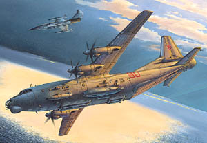
MSRP: $44.98 USD The An-12BK PPS was an aircraft with a different mission. ECM is not much talked about, and the glamour just isn’t there. Until the opponent’s air defense makes life miserable for the fighters and bombers. The Cub-C and D carried a large jamming transmitter, designed to blanket search radars on the other side of the front and degrade AAA and SAM targeting radar systems. The An-12BK PPS carries a number of external antennas, plus some interesting vents and scoops, probably for power units and cooling. The basic airframe is the An-12 Cub, analogous to the C-130 in size and mission. 4 turboprops, high wing, short/unpaved field capable, with a fair cargo capacity. Unlike the C-130, the An-12 is no longer in production, having been replaced by newer and more capable aircraft types. I did find a mention of the Cub-C/D in World Airpower Journal Volume 27, Winter 1996. It has (black & white) photos of operational Cub Cs & Ds and line drawings. The magazine disagrees with Roden on the NATO designation of the An-12 BK PPS aircraft, calling it Cub-D. According to WAJ, the Cub-D carried the huge (15 foot / 5 meter) “Sirena” jamming pods on both sides of the forward fuselage and vertical stabilizer. The An-12PP, which WAJ calls “Cub-C” did not carry these pods, which would be the big visual difference between the Cub C and Cub D. Nevertheless, this is definitely a model of an operational aircraft type. |
|
) |
) |
|
The Model I was prepared for a large box, and large sprues, having recently built a 1/72 C-130, and was not disappointed. I find the engineering thought which went into the design of the trees to be pretty inventive. There are 4 engines, so each engine assembly is on a single sprue, 4 identical sprues packed in the kit. These also include half a nose wheel (4 halves = 2 wheels), plus 1 main gear wheel (4 main wheels). If they use 4 identical molds to make these sprues, or use the same one 4 times will make a difference on how good this kit will be in 10 years. If they use this mold 4 times as much as the others, it will wear out. If they have 4 (or more) of this mold, it will hold up as well as the fuselage, wings, etc. Since the ECM pods and antennas are in sets of 2, there are 2 sprues for them. |
|
|
|
|
|
Assembly The instructions start out with multi-lingual cautions and a paint chart which gives color references for Humbrol, Model Master, Gunze Sanyo and Lifecolor paints. From there, it’s the standard pictorial instructions, with part numbers and sprue references making it fairly easy to locate and assemble parts. I followed the assembly sequence, and found another little engineering trick. Since I was spending time on step 8, the cockpit, the engine front assemblies from step 7 were getting a chance to rest before assembling the engine back assemblies in step 9. Then assembling the props (4 blades and 2 spinner parts per prop), the scoops, the horizontal stabs and the fuselage allowed the engine rear assemblies to get solid before mating them to the front in step 20. It was the engine assemblies which convinced me this is a kit for experienced modelers. I figured out how to use the cowl front to insure I got the engine front section round, but had more trouble getting the rear sections to mate securely and still have the correct circular cross section. No locating pins, not much support, and flat surfaces meeting which had to be held until everything set up. I used some putty on the back sections, mostly because I wasn’t able to keep everything together perfectly. My problem, not Roden’s. I also had to spend some time getting the mating surfaces of the front and rear engine sections to meet cleanly. They didn’t assemble with perfectly flat surfaces, so I squared them up by rubbing on a sheet of sandpaper on a table. Then I had to be careful to get the sections to line up radially. There are seam lines on the bottom of the cowl, which give the alignment, but I would have really appreciated something with a split ring on one section and a tab on the other. But how many times have you had to narrow the tab because it doesn’t line up? Again, patience will have to carry this one through. I didn’t spruce up the interior beyond painting the seats and putting the instrument panel decal on. |
|
) |
) |
|
The fuselage exterior is quite interesting. I painted the fuselage first because I knew I’d have to add the windows from the inside, and didn’t want to mask the clear parts. This is the step where you add all the scoops, exhaust ports and antennas to the front section of the fuselage. Because the kit is a modified Cub, there are no locating marks, etc. The measurements given on the instruction sheet need to be carefully looked at. I finally had to copy the drawing at 200% so I could really comprehend it. After adding all the built-in drag, I inserted the interior. It fits nicely, and I had no problem getting everything to line up with the fuselage. I particularly liked the wheel wells built into the floor board, with alignment tabs to get everything to match. I appreciate good engineering practice! |
|
) |
) |
|
The props are each 6 pieces, so it’s a little finicky to get the blades all aligned. I pre-painted the prop blades before assembly, as the section of the blade inside the hub is silver, with the inner third of the leading edge of each blade also silver. After assembly, I painted the front of each hub black, and added the yellow warning tips on each blade. The fuselage continued. I assembled the tail section, then mated it to the front of the fuselage. I left off the ECM pods because I know I would have broken the fairly light mounting brackets at least twice during the fiddling and filling required to get the tail to mate. The wing assemblies were well thought out. Each engine fits in its particular place on the leading edge. The wings have sweep as well as taper, so each engine fits slightly differently, and the left side and right side obviously are not interchangeable. I left the props off the wings, to wait until I had done all the manhandling necessary to get the wing root joints clean and smooth. |
|
) |
) |
|
The wings fit tightly against the fuselage, and the locating tabs are large and fit the holes in the wing root tightly. It’s a good thing that the locators actually put the wing in correct alignment and position. Be a shame to waste good engineering. I added weight to the fuselage here. Roden suggests putting a 100 gram weight in the forward radome, just under the navigator position. Not sure what element they’re suggesting using, but 100 gm of lead won’t fit inside that radome. I wound up punching out one of the windows and filling the compartment behind the cockpit with shot and white glue to get the nose to sit down. I put on the decals before adding the landing gear, the nose and cockpit glazing, and the antennas, pods, etc. The large decals were a handful, as the decal film is thin, and tore if I tried to move it too much. I had some difficulty figuring out where all the small decals went. There’s an enlarged drawing showing where they go, but no point of reference between the enlargement and the standard drawing. You’re left to figure out what part of the fuselage you’re looking at in the enlarged illustration. The landing gear is astonishingly robust, considering that the actual aircraft uses multiple struts. When reduced to 1/72, these become too spindly for any one to really be strong enough. But the design proves itself, and after all the struts are assembled, the gear supports the model with no rock, shake or twist. When I assembled the canopy and nose glazing, I found a big step between the canopy and the fuselage top. File, putty, sand, and repaint. I ran out of dark grey during this step, and had to buy another bottle. Finishing touches. I added the props and the ECM pods. Finished!!! A final coat of Future, and it’s ready to go to the next Craig Hewitt Chapter meeting. |
|
) |
) |
|
A look back… This was a large project for me, very ambitious. It would take lots of patience, outstanding craftsmanship, and a good deal of time to produce an An-12 which would place in an IPMS Regional. If I were going to do another of these, I would spend some time making templates from card stock to allow exact placement and alignment of the add on parts. I would spend less time worrying about panel lines. The finished model is a real attention getter, even with the single color paint scheme. This is probably the only kit you’ll ever see of this particular aircraft type. If you’re interested in Soviet aircraft, or you have any interest in AEW, this kit is a “must have”. |
|
|
Information, images, and all other items placed electronically on this site are the intellectual property of IPMS/USA ®. |
|
)
)