|
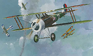
Roden Kit Number 403 1/48 Nieuport 28 |
|
|
Reviewed By Chad Richmond, #10346 |
|
|
|
|
|
MSRP $17.98 USD Roden keeps putting out kits that modelers have been wanting for years, and the Nieuport 28 is no exception. There are only 40 parts to this kit, molded in a light gray soft plastic. The trailing edges are the finest I have ever seen, requiring no thinning whatsoever. The Gnome-Rhone engine is very nicely done, as is the interior. The fabric droop is also replicated very nicely in this kit. Markings are included for 5 aircraft from the 94th Aero Squadron in March – May, 1918. Aircraft from Major John Huffer, LT James A. Meissner, LT Eddie Rickenbacker, LT Douglas Campbell, and LT James A. Meissner are the subjects on the decal sheet. The decal sheet is really nice, with everything crisp, in register, and the colors correct. However, the decals later proved to suffer from the same problems as have been reported with Roden’s decals in the past. They are brittle and will break, or even shatter when applied. More on this later. The instruction sheet consists of a total of eight pages, with very nice drawings for painting and markings. The paint reference is to Humbrol only, so if you don’t have a conversion chart, you’re on your own to choose your colors. The instructions are vague and very simple. Having reference material handy will help in several instances. And, if you’re looking for locator pins for alignment and placement, you are out of luck. Where they do exist, they are virtually nothing more than nubs sticking out. And the holes they go in to need to be enlarged. Construction begins with the engine and cowling. I sprayed all of the engine parts, firewall and inside of the cowling with SNJ. As I stated before, the engine is a beautiful representation, but be careful when separating the pushrod assembly from the sprue. The plastic is very soft and the pushrods will break very easily. There is virtually no flash on this kit, so parts cleanup is minimal. I chickened out on the painting of the cowling by choosing Major John Huffer’s aircraft. His cowling with red, white and blue striped. I sprayed the cowling and the rudder Tamiya’s Gloss White, X-2 and let it dry overnight. I also sprayed the rudder at the same time, as a decal is provided for the red and blue stripes. The next day I masked off the cowling and sprayed the blue stripe using Model Master Ford/GM Engine Blue. It was almost a perfect match for the blue used on the decal sheet. Later on, I sprayed the red stripe using Tamiya Red, X-7. It also was a prefect match. When everything was dry, I mated the cowling to the engine assembly. This took several dry fittings and a little bit of trimming to get a good fit. The fuselage is next, and is nothing more than a tube. I painted the inside of the fuselage with Misterkit Clear Doped Linen and streaked it with a brown craft acrylic for the wood effect in the cockpit area. I also applied it to the belly pan portion of the lower wing. There are no locating pins at all on the fuselage halves, so you need to go slow when joining the halves to make sure everything is in alignment. There are no locating holes or attachment points for the tail skid, and the instruction sheet is no help, so here’s where reference material comes in handy. In Windsock Datafile No. 36, it shows the mounting of the tail skid, so a little bit of plastic added to the inside of the fuselage, and you’re off and running. The mounting point for the stabilizer is flat, so this has to be trimmed to get a good fit, as does the rudder. It needs to be trimmed in order to get it to fit far enough forward. The support struts for the stabilizer are too short, and the locating pins (nubs) are straight out instead of angled, so the fit is poor. There are no locating pins for the machine guns, but the ammo chutes are aligned with a continuation of the chute on the fuselage. That is the only source of alignment and attachment. I did not do any painting of the exterior yet, but waited until I had all of the kit done in sub-assemblies. The cockpit is broken down very nicely, but here is one place that some locating pins or slots would have been very nice to have. The real aircraft’s cockpit was built out of wood stringers with metal bracket attachments. I painted all of the parts with Clear Doped Linen and then streaked them as I did the forward fuselage parts, before I glued anything together, since the cockpit is really fiddly. The seat on the actual aircraft was a solid part. I painted it brown and added some tape seatbelts. I punched out some instrument decals and put them in the instrument recesses on the instrument panel, which I had also painted with SNJ. I have read in other reviews that the instrument panel was incorrect, but it is dead on with the pictures in the Windsock Datafile. It doesn’t really matter, though, because once you get it inside the fuselage, you won’t be able to see it. The cockpit assembly slides into the fuselage tube, but there is nothing to aid in alignment, and it is very fragile, so it needs to be close, and any adjustments made using the aft bulkhead. It is accessible through both the belly and the cockpit opening. You also must cut off the forward extensions of parts 9A, 10A and 11A, or the engine assembly will not fit. They extend too far forward and hit the back of the firewall. I left the cockpit out for now. The landing gear assembly is fiddly and leaves you scratching your head. It is better to assemble everything now and make adjustments later. The wheels have an axle cap that goes on before the hub cap, to allow the wheels to turn. The cap, however, are about .030 too thick to allow the hubcap to fit. These must be thinned. I thinned mine all the way down to the end of the axle. It was at this point that I painted everything. For the Light Green, I used Tamiya XF-67, for dark Green, Tamiya XF-11. Midstone is Tamiya XF-59, Chocolate Brown Tamiya XF-10, Black was done with Tamiya X-1 and Misterkit Clear Doped Linen was used for all of the linen areas. I cut hard masks for all of the French five color camouflage patterns and then sprayed everything with numerous coats of Future. Pay careful attention to the painting guides, because even with them, I sprayed a couple of areas the wrong color, and had to do it over. Everything was allowed to dry overnight, before applying any decals. Now for the decals. As I said before, the decal sheet is beautiful. The decals come off of the backing sheet very quickly and lay down well. But, if they aren’t in the right place initially, you stand an excellent chance of the tearing when you try to move them. Even if you flood them with a lot of water, they still are brittle. I did not have too much trouble with the roundels. A lot of coaxing with Solvaset was required in about three places on each of the roundels. After about three applications and overnight drying, they laid down. When I put on the hat in the ring decals, they appeared way too big, even when compared with photographs of the real airplane. I tried to move the decal around to get it where it would look okay and it broke into about four pieces. I gave it a good try to get everything back in place, but finally took it off. There is a second set of hat markings, but they are the same size and the ring is yellow instead of red. I went through my decal boxes and found some hats on an Aeromaster Spad sheet and used them. They were considerably smaller, but they went on like all Aeromaster decals do – no problems. I had a lot of silvering problems with the fuselage numerals, but finally got them to be acceptable. The stenciling decals on the wing struts were no problem, except they needed a lot of trimming of the excess film. I tried to use the red and blue rudder stripes, but this was a lesson in utter futility. To say that these particular decals were brittle is an understatement. I had red and blue pieces of decal all over the model, me and my workbench. There was no way that these decals were going to blend with the edges of the rudder and fin. So, out came the Ford/GM blue and the Tamiya red. The painted rudder looked better, anyway. |
|
) |
) |
|
Now that all of the assemblies and
sub-assemblies were painted, it was time for final assembly. This is
where my patience wore thin, my vocabulary reverted to more descriptive
adjectives and nouns and what modeling skills I have all came together in
Roden’s Nieuport 28c1. The cabane struts do not fit the fuselage cutouts,
and there are no locating pins. I didn’t do it, but drilling out the
struts and putting in some brass rod is essential. The same holds true
for the outer wing struts. The short, soft nubs are not enough to firmly
attach any of the struts. I broke off three of the wing struts and all
four of the cabane struts when trying to install the upper wing. Brass
pins would have probably prevented this happening, plus they would have
aided in alignment. And, a word to the wise: install the rigging on the
cabane struts before installing the upper wing. This will save a lot of
frustration. Installation of the landing gear assembly suffers from the same problems as the upper wing. The lack of locating pins and the mismatch of the indentations on the firewall and lower wing complicate things greatly. This aircraft has its fair share of rigging, which is not for the faint of heart. The fuselage to wing rigging is double cable, which makes for fun. Trying to install one wire is hard enough, but to put in two that are parallel is interesting. I had drilled all of the struts and the fuselage holes prior to installation of the upper wing, which made things a lot easier. I used Orvis 8X .0035 diameter tippet material that Phil Hale gave me several years ago for the rigging. The fineness of the monofilament is dead on for this scale. It doesn’t tighten up as well when heat is applied like most monofilament, however, so I had a few problems in that area. The finished product looks like a Nieuport 28 and measures out to be very accurate according to the drawings I have. I wouldn’t recommend it to anyone that doesn’t have a lot of modeling experience or that gets discouraged easily, because this kit will tax you. However, I do plan to build at least one more, but only after installing some brass rod. My thanks to John Noack and to Roden for providing the opportunity to review this kit. |
|
) |
) |
|
Information, images, and all other items placed electronically on this site are the intellectual property of IPMS/USA ®. |
|