|
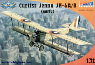
Olimp Models 1/72 Curtiss JN-4A/D 'Jenny' |
|
|
Kit Number 72001 |
|
|
Reviewed By Brian R. Baker, #43146 |
|
|
|
|
|
MSRP: $9.99 USD History Most everyone is familiar with the Curtiss Jenny, and for such a famous and influential airplane, I am surprised that more kits have not been issued of this aircraft in 1/72 scale. Years ago, Merlin Models issued a JN-4 which could be built as a JN-4A, JN-4D, or Canuck Jenny. This kit was rather heavy in detail, although it appeared to be reasonably accurate. The Olimp offering from the Ukraine is of much higher quality, and happily of lower price. The Curtiss JN-4 was undoubtedly the most famous American airplane of the World War I era, and was used in large numbers by the U.S. Army Air Service, the U.S. Navy, and the British and Canadian military as well. The process of development began in1914, when the Curtiss firm hired B. Douglas Thomas, formerly of Sopwith in England, to design a tractor biplane to replace the open pushers then in use. The first product was the Model J, powered by a water cooled Curtiss OX-5 engine rated at 90 hp. This was followed by the similar Model N, which featured ailerons between the wings, which was in turn was succeeded by the Model JN-1, a design that was really a combination of the features of both airplanes. Early models had the Deperdussin control system, a complicated mechanism involving a control wheel and rudder bar. The British disliked this system, causing its replacement by the standard “stick” control system as used today. JN-4’s were produced by both the Curtiss factory in New York and by the Canadians in Toronto, and although the designations were identical, the airplanes were not. When Canadian JN-4’s were sent to Texas during the winter for their flight training program, and operated alongside American built Jennies, the Canadian types became known as “Canucks”. These had detail differences and were readily recognizable. Incidentally, the Jenny on display at the Chicago Museum of Science and Industry is a “Canuck”, while those at the Air Force Museum and the NASM are American built versions. Examples of each type are currently being flown as antiques by private owners, and a number of replicas are also flying. Along with the Standard J-1, the Curtiss JN-4 was the standard primary trainer for the U.S. Army Air Service during World War I. It was used as JN-4A and JN-4D models, and re-engined with a 150HP Wright-Hispano, became the JN-4H. The Navy called it a JNS-1, and a JN-6H gunnery trainer also existed. Following the Armistice in 1918, thousands of Jennies were sold to civilians, and these airplanes became the basis for the expansion of civil aviation in the United States after the war. They were available at such cheap prices that it was not until 1926 and 1927 that new production airplanes could hope to compete with them. In fact, arplanes powered by war surplus OX-5 engines were common until the late thirties. Before the CAA began regulating civil aviation, barnstormers and flying circuses operated throughout the nation, giving most Americans their first glimpse of civilian aviation. If you haven’t seen the film “The Great Waldo Pepper” you should, as this is a great re-creation of this colorful era. References The story of the Curtiss JN-4 series is well told in Peter Bowers’ Profile No. 37, and there are no doubt other sources of information on the airplane. I used the internet to obtain good color photos of the OX-5 engine. There is certainly no lack of information on the “Jenny”. The Kit The kit contains 74 pieces, not all of which will be used to build a JN-4D. Olimp designed the kit for several versions, and parts are included in each kit for the JN-4A, JN-4D, and JN-4H. No parts are included for the “Canuck” but it would not be difficult to make this conversion, as it involved mainly the shape of the rudder and the inclusion of ailerons on the lower wings. The outline appears to be accurate in all respects, and although there are a lot of parts, assembly is pretty straightforward. Decals Decals are provided for an Army JN-4D at Love Field, Dallas, in 1918, and a Canadian JN-4A in Royal Navy Air Service markings in 1918. Incidentally, the JN-4A has much more pronounced dihedral than the D model, although it is possible that some were re-rigged to JN-4D specifications later in their careers. The plans do not, however, indicate the dihedral angle. I used only the decals for the instrument panel, and these disintegrated when I placed them in the water. I would suggest coating them with decal film before using them, as the color register looks good. Model I have always wanted to build a Jenny, and came close to starting my Merlin model many times. However, Olimp came to the rescue, and now I have one completed. I decided against the typical military version for one reason—my father owned and flew a JN-4D in the early twenties, and since I have one photo of the airplane, and knew the number and color scheme, I decided to build a model of his airplane. It was different in only a few respects from a standard production JN-4D. There were no wheel covers on his plane, so I had to pirate a set of wheels from a Frog Bleriot XI. The propeller in the kit was different from the one in the photo, so I took one from a Revell Fokker D.VII. In addition, the OX-5 engine was left uncowled on Dad’s airplane, so I left the cover off and detailed the engine with rocker arms, pushrods, and cooling system plumbing, which wasn’t a difficult job with a large magnifying glass. I also did not include the wingtip bows, as my dad’s plane didn’t have them. I guess it was hard to groundloop a Jenny with a tailskid. Since I didn’t use the JN-4HG cockpit cover, I put it in the box with the Revell Fokker D.VII, as I intend to do a Fokker C.1 two seat light bomber shortly, and it should be perfect for that conversion. Some details require a little work. The cockpit interior hints at interior detail, but I used electronic wire for internal bracing. Two seats are provided, along with a basic mounting framework for the sticks and rudder pedal assemblies. Flat instrument panels are also included, but you have to make sure that they line up properly inside the cockpit. Obviously, the decals should be used before the cockpit cover is installed, and these should be coated with decal film first. This is a model that must be assembled in sequence or you will have real trouble. My sequence was as follows. After detailing the cockpit, I assembled the fuselage halves and filled in the seams. I then assembled the wings, each of which comes in three sections. I set the dihedral angle by the simple method of placing a toothpick under each wingtip. This angle is the same for the upper and lower wings. I then attached the horizontal and vertical tail units, as I was not painting a multi-colored scheme. When I was sure that the units were straight, I attached the lower wing section to the fuselage. This required a bit of putty. Before I went any further, I used a thin drill to open the holes in the wing and tail unit where the bracing struts attach. This must also be done for the landing gear and cabane struts, and this is a weak point in the design. I would suggest drilling out the mounting holes for the cabane struts before putting on the cockpit cover. They need to be drilled straight down or otherwise they’ll splay out at the bottom and look funny. Also, no windshields are provided, but these are easy to make from clear plastic. Install them now or you’ll never get them mounted once the upper wing is in place. At this point, I airbrushed the whole airplane silver, as that was the correct color. I also applied the decals in the proper locations, merely four numbers on each side of the rudder and on the upper right and lower left wing panel. Once this was done, I tried a new technique that I will use from now on. Put a piece of masking tape around the whole rear fuselage, as handling this as much as you need to handle this model will literally wear off the paint. The wings are very difficult to mount, but here is what I would suggest. With the strut holed drilled out, mount the inside struts on the wings. Let the struts dry thoroughly before attempting to mount the upper wing. When the wing is mounted, it will line up at the proper angle, but you need a three view to do this. Let it dry and set up overnight. Later, when the mounting is secure, pop the outside struts into place, and then do the cabanes last. At this point, I chose to detail the engine. If you use the engine cover, you won’t need to do as much detailing, but a little sprucing up goes a long way on this engine. By the way, a cap should be installed on top of the radiator, and this is not included in the kit. Once the wings are mounted and the engine is detailed, the next step is to start the rigging process. I use electronic wire, stripped and unstranded, and started with the cabane area. There are literally hundreds of wires, it seems, and I know I missed a few. The three view drawings show some of the rigging, but not all, so a better drawing is required. Look for photos, as they will show where the wires go. EVERY strut is braced by wires, and the control cables are also braced behind the control horns. I missed an aileron cable running from the side of the fuselage to the front outboard strut top where it would connect with the pulley going to the aileron control horn, and it would be virtually impossible to install it now that the airplane is “finished”. Had I looked more closely at the photos I have, I would have installed it. After rigging the wings I installed the wires on the tailplane. I excluded the elevator control cables, as they run halfway up the fuselage where my masking tape was. These were the last wires I installed. I installed all bottom wires first, because the model could set on the top wing for this part of the process. Once that part of the process was done, it was time for the top struts and wiring. However, at that point, I installed the landing gear so the plane could finally sit on its wheels. The bracing struts, incidentally, have to be braced fore and aft, and this is not shown on the plans sheet. I suspect that about one third of the time required to build this model was spent installing the rigging wires. However, the effect of a fully rigged airplane in 1/72 scale is awesome, and the model would look naked without wires. Recommendations Olimp has done us a great service in providing this kit, especially when you consider that there are at least five different versions of the “Jenny” that can be constructed from this series. I have each one of them, and from what I learned on the first, I shall build the military versions shortly. If you are into airplanes with more than one wing, this is certainly one not to pass up. And they aren’t expensive, either. I’d get several of these while they’re available. |
|
) |
) |
) |
) |
) |
) |
|
Information, images, and all other items placed electronically on this site are the intellectual property of IPMS/USA ®. |
|