|
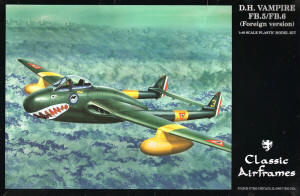
Classic Airframes 1/48 D. H. Vampire FB.5/FB.6 (Foreign Version) |
|
|
Kit Number 495 |
|
|
Reviewed By Mike Howard, #30741 |
|
|
|
|
|
MSRP: $45.00 USD
The DeHavilland Vampire was the first single engine jet fighter that was placed into production by the British. It saw a long and varied service life in air forces of as many as 28 different countries outside of the U.K. Some of these aircraft flew as late as 1990 in their military capacity. Some can still be seen on the air show circuit, over 50 years after the planes inception. Classic Airframes has released several versions and boxing of the Vampire to date, with a much better rendition of the classic airplane than had been previously seen in injection molded plastic. This particular boxing allows the builder several different version and markings options: 2 different FB.31’s from the Royal Norwegian Air Force, an FB.52 from the Royal Norwegian Air Force, an FB.3 from the Mexican Air Force (this reviewers choice for this build), and 2 different marking versions for a Swiss FB.6 (along with the required modification parts). The original boxing of this kit apparently had some issues with the shape if the wing mounted engine intakes. The version that I received had addressed this with a new set of resin cast intakes (in addition to the original “misshapen” set). The kit comes in 2 sprues of fairly soft gray plastic and lots of nicely cast gray resin. The resin is in 2 separate bags, 1 with the original set of parts and 1 with the new intakes and the foreign version specific parts. The clear parts (windscreen and canopy) are very nicely molded and very clear. The decals also are quite thin and cover all of the aforementioned options. (In the pictures, some of the resin cockpit parts have been painted RLM 66 and some plastic parts removed for dry fitting. Sorry, I couldn’t help myself!!) |
|
) |
) |
|
The detailing on the cockpit parts is very nice and crisp. My only
complaint is that the instrument panel doesn’t have raised details and
there are no decals to fill in the blank instrument faces. There’s also
a supplemental instruction sheet for the various differences on each
export version that deviates from the original kit instructions. On to
the build: The cockpit is the starting point for the kit and I found the instructions somewhat vague as to exactly what is the pour stub or the defined part. Where to cut the forward floor section for proper fit was also a “best guess” activity. A little dry fitting of the floor and front panel gave me a good starting point. A bit more cutting, sanding and dry fitting was done to get the parts to fit where I thought they should be. Once that was done, the cockpit floor was placed against each fuselage side and its location marked with a very fine line marker. This gave the locating points for the cockpit side panels. Each side panel was painted and the super glued (CA) to their respective fuselage half. Prior to the glue completely setting, I verified the location by placing the cockpit floor in position and making final adjustments. |
|
) |
) |
| The instrument panel was next on the list of required items and, as previously mentioned, required some extra work to get the instruments looking acceptable. I put a set of Mike Grant Instrument Decals to use and, with the aid of a punch set, found them to be just what was needed. | |
|
|
|
| The instrument panel was then glued to the cockpit floor and set aside to dry. Another piece that requires fitting prior to joining the fuselage halves is the engine face/bulkhead panel. A little filing and sanding was required to get this panel to match the fuselage interior shape. I also painted the turbine blades silver and used a black oil wash for detailing. This piece was glued into one side and then the halves temporarily mated to ensure proper alignment of this panel. The kit exhaust tube is a two part plastic affair and even after much dry fitting and tweaking came out in an oblong cross section rather than round. Digging around in the scratch building pieces and parts drawer uncovered a section of brass tubing that was the proper inside diameter to match the turbine face, but a little large on the outside diameter. If I wanted the fuselage halves to join correctly, I determined that some plastic was going to need to be removed from the exhaust section of the halves. The handy Dremel tool, with a medium grit sanding drum made short work of the excess plastic and soon the brass exhaust tube was in place with the fuselage halves now touching each other when placed over the tubing. | |
) |
) |
|
I left enough space on the inside of the exhaust area to allow the brass
tube to be placed after assembly and painting were complete. This would
save a bit of masking work later on. The fuselage halves were now
joined, glued and clamped to sit overnight and dry. I used CA on the
resin interior-to-plastic fuselage parts and Tenax on the plastic to
plastic joins. One thing to mention here: the front cockpit floor
section/nose wheel well was not yet glued to the main floor section. As
I had some doubts about where it should exactly be located, I thought it
best to wait until I could positively identify its final location after
the fuselage halves were together. The slide fit of this part to the
main floor made this process a little more forgiving. Also, as the
instructions don’t specify how much nose weight would be required, I
opted to leave the bottom gun panel off as another area where weight
could be added. While the main fuselage was left to dry, I moved on to the tail booms and the wings. The tail booms are actually a nice fit as far as the alignment goes, but each side required a little filling where the rudder portion of the join is located. Since this kit has no alignment pins, a little patience and care go a long way towards minimizing filling and sanding of these parts. |
|
|
|
|
| The wings require the resin wheel wells to be attached to the lower wing half prior to adding the upper half. Again, dry fitting is the key here. I had to sand off quite a bit of the top side of the wheel well to allow the wing halves to close properly. You also need to pay close attention to the placement of each wheel well as there isn’t a real positive location that sets the proper alignment. The wing tips are separate parts from the wing halves. There’s an option for a short or long tip and the instructions only suggest “Check your references for the proper style of wing tip” as your guide for which ones to use. My Vampire references are quite limited so I used a combination of the kit painting guide and some internet research to determine the longer of the options would be correct for the Mexican Air Force version that I’d decided upon as a final product. The resin intakes are the final wing component that needs to be attached prior to being able to mate them to the fuselage. Here again is an area where the instructions aren’t real definitive as to where the intake begins and the resin pour stub ends. I of course cut these a little shorter than I should have and had to use some plastic card to help fill in the gaps. | |
) |
) |
|
While all of these parts were drying, the fuel tanks got some attention.
These were well molded and lined up nicely also. A little Tenax along
the join and some more clamps (I need to buy more of these things).
These are specifically right and left handed tanks, so I also marked
them accordingly with a fine tip marker. Landing gear legs were removed from the sprues and mold lines were removed. The front gear leg parts (2 of them) were assembled and glued. All of these parts, along with the inside of the gear doors (nose and main gear) and wheel wells were sprayed with non-buffing Testors Aluminum Metallizer. I’m still a big fan of these paints as they dry very quickly and have a wide variety of shades. A return to the now dry fuselage started the next build session. I moved the resin nose wheel well into it forward most position and used CA to secure it there. A little bit of seam work was needed, followed by some re-scribing of panel lines, where required. A couple of revisits to the area around the exhaust tube were required to get this join both strong and to make the seam finally disappear. The wings and tail booms got the same attention until I was happy with the results. The seat was painted and some tape seat belts added prior to installing. Attaching the wings is a stepped butt joint, but actually ends up pretty strong once the glue dries (lots of gluing area). Care and lots of dry fitting are the requirements to determine how much of the wing join area is flash. The cross section of the wing matches the stepped fuselage location quite well requiring little to no filling. The area around the intakes is another story. Since too much of the resin intake was removed, the plastic card that was used as filler also had to be sanded to match the fuselage contour. I prefer doing it this way rather than just filling a wide gap with either CA or putty. |
|
) |
) |
|
The remaining gaps were filled with a couple of applications of Mr.
Surfacer 500 and then sanded smooth. This is when I really noticed how
soft the plastic was as even a medium grit sanding stick left pretty
deep marks. This would be the first twin tail boom aircraft that I’d built in recent history (the last time I remember building one was when the Monogram P-61 was a new kit!) so I wanted to approach this section of the build with care. The horizontal stabilizer was clipped from the sprue and the mold lines removed with a little sanding. This part is also a butt joint between the 2 booms. The booms have a stepped locator where the open end of each boom fits, but the wing recesses are not evenly molded. Some scraping/gouging/cutting was required to get them to fit flush together. Tenax was applied to each tail/wing join and a rough alignment done on each boom. This was left to dry for approximately 10 minutes and then the stabilizer was mounted between the booms. A large clamp was placed against each rudder and the stabilizer was aligned and then the clamp secured to hold everything in place (or so I thought). When I came back to this the next day I found that there had also been some lateral torque applied to the booms and they were no longer in proper alignment. Lacking any better idea, I through caution to the wind (first making sure that the wind wasn’t blowing back into my face) and applied heavy doses of Tenax to each boom-to-stabilizer joint. To my pleasant amazement, this softened the join up enough to allow a counter torque clamp to be applied. I monitored this closely and once the molten plastic started to harden, I removed most of the clamping pressure. All was again left to sit. When I came back to work on the kit again I was very happy to see a near perfect main wing-to-stabilizer alignment! |
|
|
|
|
|
Now that all of the main parts were attached, it was time to see how much
weight would be needed to make this beast sit properly on its tricycle
landing gear. The small area available in the nose had already been
stuffed with small split shot fishing weights, but this proved to not be
nearly enough. With some larger split shot, I started adding to the gun
bay area, directly behind and below the cockpit. Four iterations of
adding and balancing on the landing gear were required before the nose
dropped forward lightly. I added a couple more small weights for good
measure and, after the CA had dried, glued the gun bay panel in place.
I’d read in a previous review, that this was a horrible fit.
Fortunately mine was just the opposite. The panel required only a few
swipes with a sanding stick to achieve a perfect fit with no gaps at all
and all corners level with their respective fuselage sections. Now we’re finally getting somewhere, so it is time to start some paint prep. The color guide for the Mexican Air Force Vampire gives a very vague “Dark Green” description for the main color (this color was a complete wrap around scheme). Some online inquiries and research turned up many different answers, but little definitive information. I finally decided on a Gunze IJA Green for my choice of colors. On the first pass I only sprayed the assembly joints to check the filler work. Only a couple of areas required some additional attention, which I was pretty happy with. The color scheme that I chose has yellow bands on both the wings and tail booms and completely yellow wing tanks. These areas were marked out and sprayed with Gunze RLM 04, allowed to dry and then masked for the striping. The wing fuel tanks were also sprayed this color after seam work and some re-scribing. The IJN Green was thinned (1:1 with 91% ISO alcohol) and spayed over both the top and bottom surfaces of the plane along with the gear cover doors and the canopy. One of the trickier parts of the Mexican scheme is painting the red area beneath the “shark mouth” prior to decal placement. Several approaches were considered and I finally settled on scanning the decal sheet and making a mask from the scan. The mask was cut out and then transferred to some 3M blue masking tape. This was placed on the nose and then the red sprayed. |
|
) |
) |
|
Ultimately this didn’t end up exactly where it showed on the instructions,
but was close enough. This was allowed to dry overnight and then a
couple of coats of slightly thinned Future were sprayed on as a gloss
coat for the decals. The kit decals went on very nicely with a little help from some Micro-Sol setting solution. The teeth of the shark’s mouth lined up very well with the painted red area and required only a couple of small paint touch ups. The decals were allowed to dry overnight again. The surface around the decals was wiped clean with some warm water to remove any decal glue residue and more drying time allowed. Another couple of light coats of Future were then sprayed to help blend the decals in (and even more dry time). The next step was a complete overspray with Testors Dullcote lacquer. I usually thin this down approximately 50% with lacquer thinner and spray on a couple of coats (and yes, more dry time). Here’s where some issues cropped up. The painted areas didn’t dull down as much as the decaled areas. Most of the decals looked okay, but there was one that suddenly looked to be very badly silvered. I tried making many small cuts in the decal surface with a new scalpel blade and reapplying some more potent decal solutions, but no improvement was seen. |
|
|
|
|
|
Ultimately the decal was sanded off, some touch-up paint sprayed and more
dull coat applied. I also sprayed a couple more layers of dull coat
over the entire plane to see if that might help with the differences in
sheen. The top side seemed to improve, but some of the smaller
stenciling on the bottom still stood out a little. Some sludge wash was applied to the panel lines and the cleaned up accordingly. All of the final little remaining bits were added (landing gear, counter balances, pitot tube and gear doors). Since there are no marked locations for the wing fuel tanks, and the instructions are not consistent for the placement location, I did a “best guess” as to where these should be located. To help stabilize the mounting points, holes were drilled into the wings and tanks to allow a piece of brass tubing to be inserted for added strength and to fix the mounting location. A small piece of acetate was cut and added to the gun sight for the reflector glass (almost forgot this). Finally, the wingtip lights were painted silver and then over-coated with Tamiya clear red and blue. This is the one area that I felt could have been a little better engineered. The real aircraft had large clear lenses with colored bulbs in them. While not difficult to scratch build, it would have been nice to see some additional clear parts for these. |
|
|
|
|
|
|
|
|
|
|
|
In summary, this was a fun and somewhat challenging kit to build. You’ll need to determine which version you want before you start and lay out the required parts accordingly. Though this is to be considered a limited run kit, it’s definitely not beyond the capabilities of an average modeler that isn’t afraid to apply their vaunted “modeling skills”. Time, patience, some careful planning and lots of dry fitting will go a long way towards making this an enjoyable build with a great end product. Thanks very much to Jules Bringuier at Classic Airframes for the review sample and please keep producing the great subjects that you have been over the years! |
|
|
Information, images, and all other items placed electronically on this site are the intellectual property of IPMS/USA ®. |
|
)
)
)
)
)
)
)
)
)
)